GDO is my project starter in this year 2012, even it is actually not a new one. I only grade up my old gdo that I built from plastic box and have only 2 band coil , for 80 m and 40 m. Now it can be used for HF band from 1.6 up to 30 Mhz. The schematic I take from " Modern GDO " ( QST May 2003 ), but I use only the oscillator.
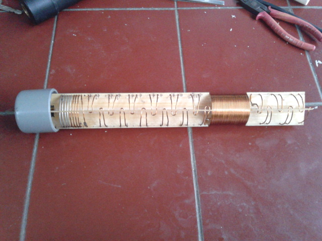
The box is made from PCB with final touch of paint, and coil core is from sewing thread that I put audio connector to make easy to plug in to GDO. I use heat shrink rubber to keep the coil fix in the position and for nice looking. The dial mark I used from transparent paper by mirror printing then glued with silicone paste.

The lowest frequency should be lower than that , seeing that my project is still around 3.5 - 21 Mhz only, for the moment I just put in any limit for lowest and highest frequency for hf operation, and if my project needs lower or higher , I will re-wind the coil then.
This Frequency Counter I built totally from IK3OIL
( schematic and source code ).For normal operation it can measure up to 50 Mhz, and needs prescaler for higher measurement. I like IK3OIL project ( FC ), because he provides some variables choice for the PIC Program, eg. X-tal, prescaler division , etc. so I can use any X-tal from the junk and prescaler IC, as well. I know, to get prescaler IC is not easy unless importing from other countries. Another way to get it, is, by cascading two ic LB 3500 ( 1/8 prescaler ) , it becomes 1/64 prescaler. Even it is only 150 Mhz, but better than not.