Thursday, June 28, 2012

HOME MADE MOTOR POWERING MOUNTING BRACKET

This is my experimental mounting bracket for mobile antenna using car POWER WINDOW's motor . The construction is simple, you can see it, the only hard job is positioning the axle of motor and hinge, it must be one line. You may change the hinge with simpler and light one. My purpose putting the hinge is only for keeping the load of antenna, not at the motor. I make an octagonal hole, just like a 19 mm spanner by filing as arm adapter for matching to the gear at power window. Don't do welding because the gear inside is made from such kind of plastic material.


 It is more detail picture of motor, arm coupling and 90 degree stopper. The long bolt is for coupling adjustment or replacement.
You can see the plate connection from motor to the hinge for connector placement. Don't forget to make stopper for hinge rotation, I make 90 degree operation.

The total weight is around 1 kg, so you must consider about it.


This is maximum position for standing.


and it is minimum position.

I am using a simple motor speed controller with some adjustment, but still need improvement for movement. because down speed  movement is faster than up movement ( because of antenna self weight ), so I add Resistor to keep slower for down movement ( same speed is the best ),
I am sure you know better for this matter to solve it.

Tuesday, January 24, 2012

GDO

GDO is my project starter in this year 2012, even it is actually not a new one. I only grade  up my old gdo that I built from plastic box and have only 2 band coil , for 80 m and 40 m. Now it can be used for HF band from 1.6 up to 30 Mhz. The schematic I take from " Modern GDO " ( QST May 2003 ), but I use only the oscillator.
The box is made from PCB with final touch of  paint, and coil core is from sewing thread that I put audio connector to make easy to plug in to GDO. I use heat shrink rubber to keep the coil fix in the position and for nice looking. The dial mark I used from transparent paper by mirror printing then glued with silicone paste.


The lowest frequency should be lower than that , seeing that my project is still around 3.5 - 21 Mhz only, for the moment I just put in any limit for lowest and highest frequency for hf operation, and if my project needs lower or higher , I will re-wind the coil then.


This Frequency Counter I built totally from IK3OIL
( schematic and source code ).For normal operation it can measure up to 50 Mhz, and needs prescaler  for higher measurement. I like IK3OIL project ( FC ), because he provides some variables choice for the PIC Program, eg. X-tal, prescaler division , etc. so I can use any X-tal from the junk and prescaler IC, as well. I know, to get prescaler IC is not easy unless importing from other countries. Another way to get it, is, by cascading two ic LB 3500 ( 1/8 prescaler ) , it becomes 1/64 prescaler. Even it is only 150 Mhz, but better than not.


Friday, November 4, 2011

MY FIRST SDR

 Thank to YU1LM , I can finish my home project, SDR that I take and learn from your articles. As it is the first, I do it by making pcb from the schematic ( not from provided copy ).


 This is TX part of pcb placement


RX part


Thursday, June 9, 2011

40M MOBILE ANTENNA ( Construction Detail Crossed PCB Core )


This another style of making Coil core for 40m mobile antenna, it is little bit complicate compared with PVC core, because you have to prepare a pair of teflon instead of PVC cap with accurate fabrication, and also 2 pcs of PCB for making core.


If you want to make it quickly, you just copy , follow its dimension and do as I show in photo .

Make cross cutting for PCB insertion

Top Teflon with Whip holder

Top View, the aluminium plate is for capacity hat

  
Matching Coil

Complete winding

PVC Cover

 Don't forget to remove copper layer at PCB. Cross and glue . One thing I still get problem is how to glue teflon to PVC, for the moment I use screw to fix it, and also for base connector, I drill the teflon and screw to hold the connector avoid of loosing .

Wednesday, June 8, 2011

40M MOBILE ANTENNA ( Construction Detail PVC Core )

Base Connector
Here I try to explain how to construct it step by step :
Prepare all the material :
- 2 meter Larson antenna ( set )
- PVC Pipe 1-1/4 inch 30 cm long ( Incl. the cap )
- Resin
- Copper Wire 1.5 mm dia.

Take 2 m antenna connector and whip holder . 
Make a hole just fit to the connector diameter at the PVC cap, and smaller hole just fit to whip holder size at the other PVC cap. 
Solder outer and inner connector with cable about 10 cm long. Now fix it to the hole and put thin glue around the connector to avoid of resin leakage.

Don't forget to prepare of another cap, otherwise you will do mixing of resin twice, and double works of pouring. One thing I forget to tell you, make inside cap surface rough enough, if neccessary you can add something like anchor mounted at the connector body by soldering some cm of copper wire.
Base Connector
After preparation  this job is OK, you can start pouring  resin on it.
If you are not familiar with resin work, ask chemical store to guide you how to do, especially for mixing. Don't repeat my bad experience , the resin never dry and leakage somewhere around  base connector. It is because of poor mixing and less activator.
Now you can see the connector from bottom side.
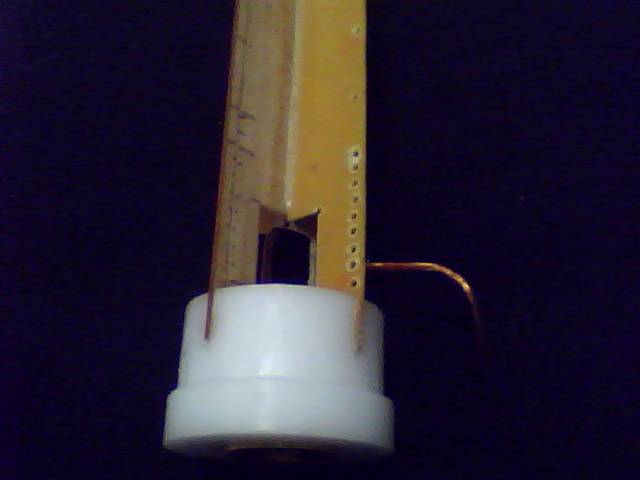
 
Whip Holder


It's the whip holder. You can see the whip going through the holder, I think it will be easy to adjust the whip up and down freely, to get wide range of resonance, but is a big mistake, I found it after some weeks I used it. The rain water come into inside and make SWR very high. So, now I change its style , I close the whip holder with strong solder, yes, the whip almost can't be adjusted, but it can make me relax.
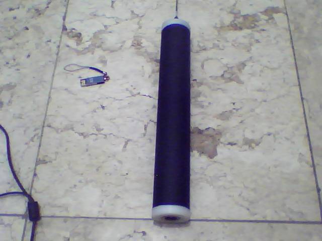
Winding Style
Now, it's very easy job to do. Make a hole for starting of winding of 44 turns ( but you can make more turns for easy adjustment). You can start it 2 cm from top ( for cap insertion space ), wind the wire closely, tape strongly for holding it then make another 5 or 6 turns up to matching coil end.
The matching coil is 8 turns with one wire space and tapping point is 3 turns from ground side.
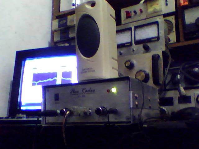


Ready to adjust
Now is ready for adjustment.
If you don't have antenna analyzer, you may use Grid Dip Meter and SWR meter, because it is very easy job.
Place this antenna to where the antenna will be installed. Make sure all the grounding system is already installed perfectly. First, bracket itself must be grounded ( with lead wire ), the doors must be connected to the car body. Don't do adjustment in garage , go to an open area for easy to get good result. If everything is OK, you can check with GDO by making loop wire at end fed to get frequency resonance. Keep all winding and whip just like that posistion. The adjustment is only at top winding
by adding or lessen the turn. If you are sure with frequency you choose, now connect to TRX and try with small power to check SWR. Slight tapping point slowly until you get the lowest SWR. Yes, now wrap it with heat shrink rubber and seal in some places like whip holder and edge of heat shrink. Good Luck.